

ESP8266 WiFi IOT chip | Programing the Firmware
27 Jan 2016ESP8266 is a cheap WiFi chip you can use in your embedded projects. You can communicate the chip using AT commands through UART. You can setup a WiFi hotspot, connect to an existing WiFi network, act as a web server, send data (TCP/UDP). The real fun is that you can reprogram the whole chip and you don’t need an other micro controller to control it. The ESP8266 ES1 come with 2 GPIO pins. There are other variants of this chip with more GPIO. This ESP 01 cost around Rs. 250 which is so cheap while comparing with other WiFi modules.
One thing to remember is that the device is 3.3 V logic. Do not connect 5V supply or 5V RX/TX pins to the device.
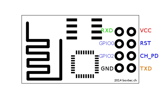
Connection
VCC -> 3.3V
GND -> GND
CH_PD -> 3.3V
RX -> TX
TX -> RX
If you are using a USB/TTL serial connector try to power the device separately using a 3.3 V supply (Needs >200mA).
These are the list of AT commands that is supported. (Link) But some variations will be there (depends on the firmware you are using). Here is a good post that talks about the AT commands. (Link) If you are talking to this chip using putty or minicom (Linux) then you need to press Cntrl+Enter to send a line feed. The real beauty of this chip is that you can change the firmware and flash it. The ESP8266 has a 40 Mhz chip in it and several GPIO pins (2 for ESP 01) which you can configure just like a micro controller. Going through the forum and figuring out the right firmware, tools and referring the SDK user manual is really painful. But you will get the hang of it. This forum (link) is exclusively for this chip. There are several flavors for programming this chip also. There is also a micro python library for it. The one which is easy is using an aurdino IDE. Refer this site (link) to get started. You need esptool when trying out different firmware in order to burn. (link)
Connection (Flashing the Device)
VCC -> 3.3 V
GND -> GND
CH_PD -> 3.3 V
GPIO0 -> 0 V
Reset -> GND
RX -> TX
TX -> RX